Shandong Fengtu IOT Technology Co., Ltd
Sales Manager:Ms. Emily Wang
Cel,Whatsapp,Wechat:+86 15898932201
Email:info@fengtutec.com
Add:No. 155 Optoelectronic Industry Accelerator, Gaoxin District, Weifang, Shandong, China


Sales Manager:Ms. Emily Wang
Cel,Whatsapp,Wechat:+86 15898932201
Email:info@fengtutec.com
Add:No. 155 Optoelectronic Industry Accelerator, Gaoxin District, Weifang, Shandong, China
Model:FV3
Brand:fengtu
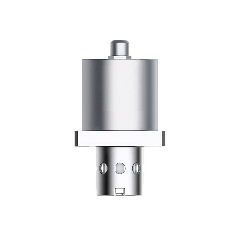
1、Oil viscosity sensor Product Overview
Oil viscosity sensor can automatically detect three indicators of oil in real time: density, viscosity, and temperature, providing early warning of contamination and aging, and optimizing oil change intervals.FV3 Oil viscosity sensor utilizes a piezoelectric resonant MEMS core element, integrating high-precision signal acquisition and processing units with intelligent algorithms to enable the real-time, simultaneous measurement of liquid temperature, dynamic viscosity, and density.
Application Areas: Hydraulic power units, gearboxes, diesel engines, turbines, air compressors, and similar equipment.
2、Oil viscosity sensor Applicable Oils
Industrial Lubricants: Hydraulic oil, gear oil, turbine oil, transformer oil.
Engine Oils: Diesel engine oil, aviation engine oil.
Light Fuels: Gasoline, kerosene, aviation fuel.
3、Oil viscosity sensor Measurement Principle
The FV3Oil viscosity sensor operates based on the principle of piezoelectric resonance. Driven by an electronic unit, its core oscillator maintains a state of resonance; by precisely measuring changes in characteristic parameters—such as resonance frequency, phase, or amplitude—the device directly calculates the viscosity, density, and temperature of the medium.
Its oscillation period T is correlated with the liquid density: ρ = K0 + K1*T + K2*T² (where K0, K1, and K2 are instrument calibration parameters).
Its oscillation quality factor Q is correlated with viscosity: η = C0 + C1*Q + C2*Q² (where C0, C1, and C2 are instrument calibration parameters).
Kinematic viscosity can also be derived using the following formula: µ = η / ρ (where µ represents kinematic viscosity in mm²/s or cSt; η represents dynamic viscosity in mPa·s; and ρ represents density in g/cm³).
4、Oil viscosity sensor Technical Parameters
| Measurement indicators | Range | Resolution | Measurement accuracy | |||
| Temperature | -20~125℃ | 0.1℃ | ±0.3℃(25℃) | |||
| Dynamic viscosity | 1~400cP | 0.1cP | ±3% | |||
| 0~1000cP | ||||||
| Density | 600~1250kg/m3 | 0.1kg/m3 | ±3% | |||
| Note: The factory default is calibrated according to 68# hydraulic oil. (Customized calibration of oil products is available) | ||||||
| Electrical parameters | ||||||
| Digital signal output | RS485 MODBUS RTU (default) | |||||
| Simulated current output | 4~20mA (optional) | |||||
| Working voltage | DC12~32V(RS485) | DC20~32V(4~20mA) | ||||
| Working current | <20mA (RS485 output) | <40mA (4~20mA output) | ||||
| Electrical interface | M8*1, 6-core aviation plug | |||||
| Connect the cable | 6 (core) * 2 meters (standard), 26AWG | |||||
| Refresh time | 1 time/S (power on < 30S) | |||||
| Follow the standard | EN61326-1 | |||||
| EN61326-2-3 | ||||||
| ICES-003 B-level | ||||||
| Temperature parameters | ||||||
| Working temperature | Fluid temperature | Storage temperature | ||||
| -30~70℃ | -20~125℃ | -40~85℃ | ||||
| Structural parameters | ||||||
| Mechanical interface | Structural dimensions | Probe material | Protection level | |||
| Flange (see product structure diagram) | Φ32*56.6mm | 316 stainless steel | IP65 | |||
| Other parameters | ||||||
| Probe allows pressure | The probe allows flow rate | Sensor weight | ||||
| ≤2MPa | ≤3m/s | 150g | ||||
| Communication protocol-cable | ||||||
| red | White | Black | Green | Brown | Blue | |
| DC24V+ | RS485+/A | GND | RS485-/B | 4~20mA ch1 | 4~20mA ch2 | |
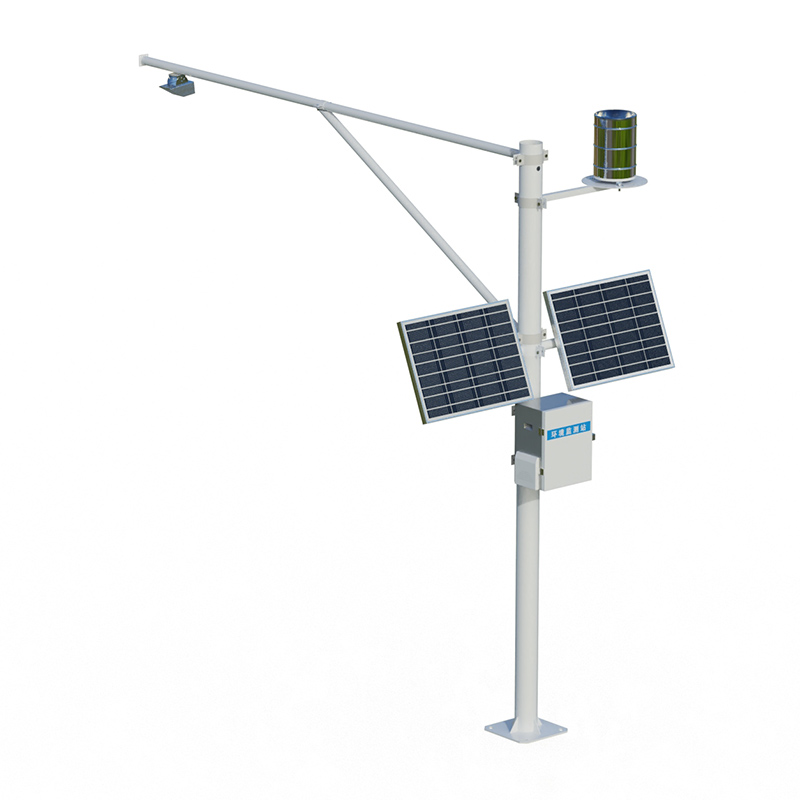
best weather stations are used to monitor wind speed, wind direction, temperature, humidity, air pressure, light, optical rainfall, pm2.5, pm10, noise, and other meteorological elements....
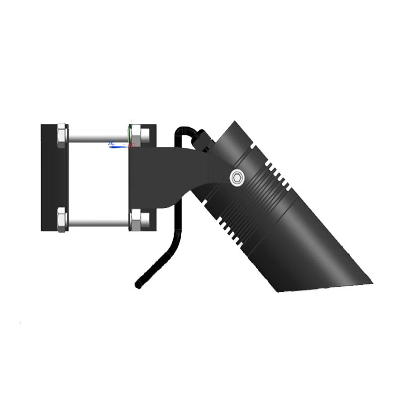
Visibility in tunnels is something to be concerned about.Visibility inside tunnels is low, especially at entrances and exits, so drivers should always stay alert and turn on their headlights in advance so that they can stay safe even in low visibility conditions. At the same time, they should pay at...
Windway introduces the 10-in-1 Micro Weather Meter, a solution to the challenges of environmental monitoring. This device is capable of comprehensively monitoring key environmental indicators such as temperature, humidity, barometric pressure, wind speed, wind direction, illuminance, rainfall, noise...
weather measuring instruments and their uses are scientific and technical equipment specially used to observe, measure and monitor weather and climate, mainly thermometer, barometer, rain gauge, wind vane, anemometer and so on....


 Get a Free Quote
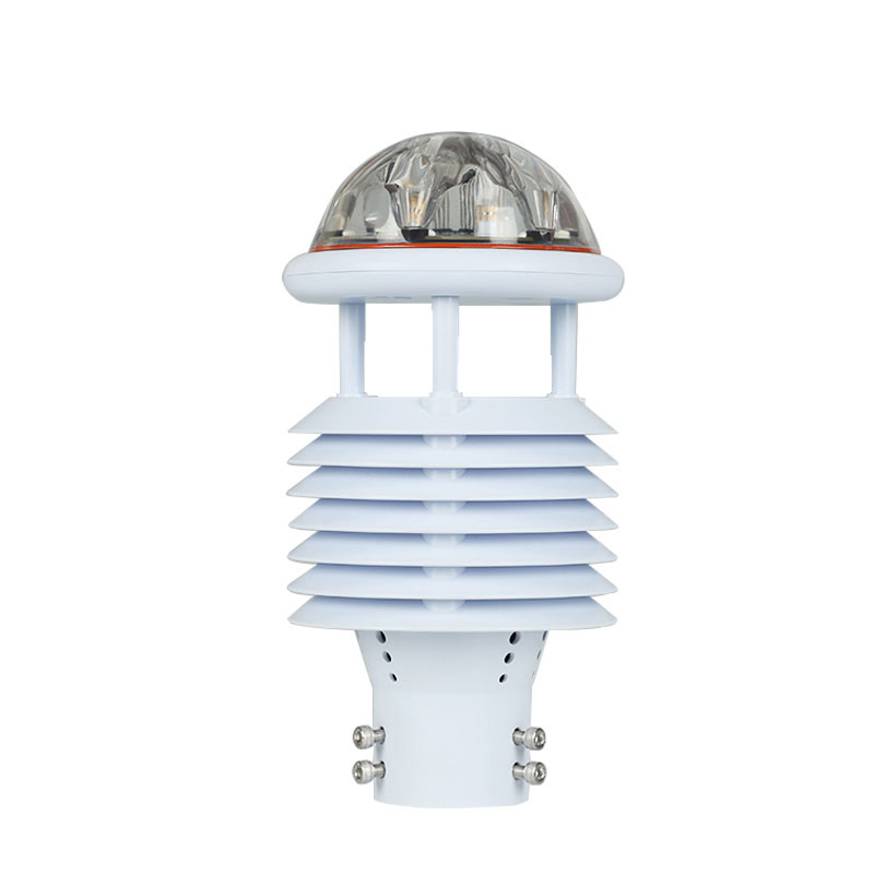
 Skype
Skype
 whatsapp
 mail
mail