Shandong Fengtu IOT Technology Co., Ltd
Sales Manager:Ms. Emily Wang
Cel,Whatsapp,Wechat:+86 15898932201
Email:info@fengtutec.com
Add:No. 155 Optoelectronic Industry Accelerator, Gaoxin District, Weifang, Shandong, China


Sales Manager:Ms. Emily Wang
Cel,Whatsapp,Wechat:+86 15898932201
Email:info@fengtutec.com
Add:No. 155 Optoelectronic Industry Accelerator, Gaoxin District, Weifang, Shandong, China
time:2025-03-04 09:17:13 source:Weather Station viewed:773 time
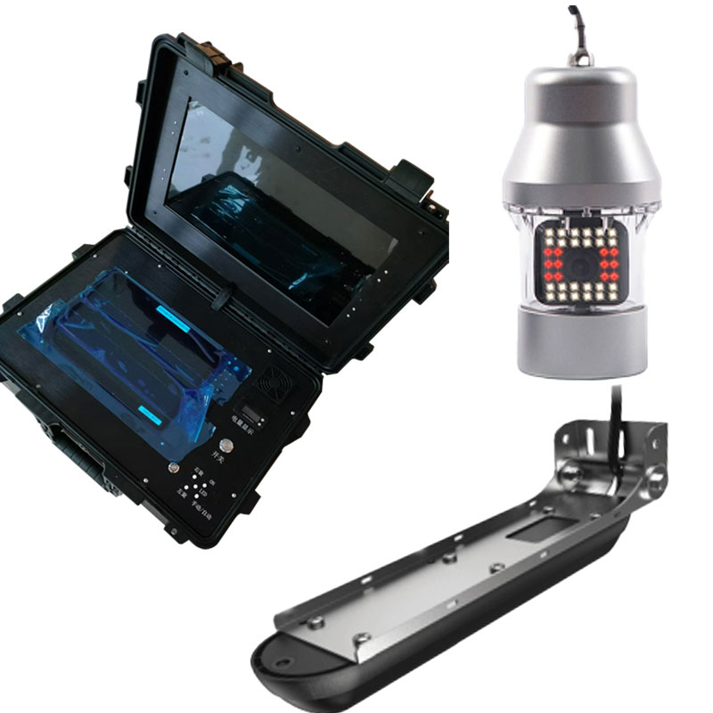
During all stages from the production to the usage of photovoltaic modules, various defects in solar cells may occur, such as broken grid lines, leakage, black heart wafers, missing corners, cracked wafers, poor soldering, short circuits, etc. These defects are difficult to detect with the naked eye, but they can severely affect the performance of the modules, reduce the power generation efficiency, and even pose potential safety hazards. The Solar Panel Tester based on EL (Electroluminescence) detection can accurately identify these defects, effectively control the product quality, ensure the stable and efficient operation of photovoltaic power plants, and reduce the later maintenance costs.
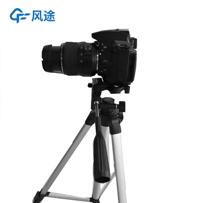
The detection principle of EL technology is based on crystalline silicon solar cells. When a forward bias voltage is applied to the solar cell, the power source injects a large number of non-equilibrium carriers into the crystalline silicon cell. These carriers continuously recombine and emit light, releasing photons, and the emitted light is infrared light. Then, a CCD (Charge-Coupled Device) camera is used to capture the photons, and after being processed by a computer, an image is formed. However, the entire test must be completed in a darkroom environment. Since the brightness of the EL image is proportional to the current density, the defective parts will appear black or gray in the image, and the cause of the defect can be determined accordingly.
Detection Process:
Place the photovoltaic module steadily on the platform and correctly connect the EL tester to the module. If it is in an outdoor strong light environment, an infrared-proof darkroom tent needs to be set up; if there is no strong light indoors or at night, the subsequent operations can be carried out directly.
The tester applies an appropriate forward voltage to the photovoltaic module to prompt the module to generate the electroluminescence phenomenon.
Rely on a high-sensitivity CCD camera to capture the infrared light emitted by the module, thus generating an EL image.
Use professional image processing software or artificial intelligence algorithms to analyze the EL image, identify the type, location, and severity of the defects, and output a detailed detection report.
Common Types of EL Image Abnormalities
Broken Grid Lines: The broken grid lines here are not the same as the broken grid lines in the types of solar cell grid lines (in which a small amount of silver paste is used on both sides of the main grid line to connect the main grid line and the fine grid lines). Instead, there are breakpoints in the printing of the main grid silver paste, resulting in an open circuit between the fine grid lines and the main grid line on the solar cell, making it unable to conduct electricity. In the EL image, it appears as a thick black line perpendicular to the main grid line, usually caused by abnormal screen printing of the solar cell, and has little to do with the welding equipment.
Leakage: During the printing of the solar cell, if there are scratches or cracks on the surface of the silicon wafer, the silver paste will seep into the PN junction position of the solar cell along the gaps during the printing of the front silver paste. When the power is turned on, this area appears black in the EL image, and the solder ribbon can be seen in the EL image because the solder ribbon conducts electricity.
Black Heart Wafers: The black part in the EL image is the aggregation of point defects, which originates from the production period of the silicon rod. This material defect will reduce the concentration of non-equilibrium minority carriers in silicon, thereby weakening the EL luminous intensity in this area. The common black "patterns" in the EL image of polycrystalline silicon are also caused by the dislocation of silicon crystals. This problem is generally caused by improper temperature control during the production of the silicon rod/ingot and has nothing to do with the welding equipment.
Missing Corners: During the handling of the solar cells or the production of the modules, the silicon wafers are prone to cracking due to their brittleness. The silver paste at the cracked part is broken and cannot conduct current, and it appears black in the EL image. The factors that may cause missing corners in the equipment include problems with the battery box columns, wear of the photographing platform, improper rear movement of the middle position, too low H3 position, inappropriate position of the solder ribbon bending, inappropriate position of the robotic arm's wafer lifting position of the laminating machine, etc.
Explosive Cracks: These mostly occur in the modules after lamination, that is, they are commonly seen during the final EL test. Usually, it is caused by excessive force of the framing machine during framing or the module falling from a height, and it rarely appears in the previous EL test.
Hidden Cracks at the Front Indentation and Rear Indentation after Lamination: For densely-gridded modules, when the EVA weight is lower than 560g/㎡, or the solder ribbons at the front and rear indentation are too short, this kind of hidden crack may occur.
Poor Soldering: It appears as a gray shadow in the EL image and is easily confused with the dislocation pattern of the solar cell.
Single Cell Short Circuit: It is divided into front short circuit and rear short circuit. For the front short circuit, it is necessary to check the crystallization situation of the flux inside the H1 hand gripper and the guide cover plate; for the rear short circuit, it is necessary to check whether the pressing tool presses the solder ribbon, or whether the solder ribbon slips due to not being cooled in time after welding. At this time, this solar cell appears black in the EL image and cannot be displayed.
String Short Circuit: It appears as two battery strings completely disappearing and showing black in the image. Generally, it is caused by the overlapping of the busbars, and it is necessary to check the length of the busbars of the laminating machine and whether the EPE strips completely separate the long and short strips.
Residual chlorine, pH value and temperature are important indicators for measuring water quality. The residual chlorine content reflects the disinfection effect of water body. If it is too low, it cannot effectively kill bacteria, and if it is too high, it may be harmful to human health. The pH valu...
Micro monitoring station is an integrated weather sensor launched by Fengtu Technology, which adopts integrated structure, compact design, easy to carry, five-proof body, safety and environmental protection. The product can be used to detect the concentration of tiny particles in the atmosphere, but...
-- Preface --Why do humans measure wind speed and direction? In fact, it has a long history.From the ancient Chinese Xiangfeng Tongwu to the ancient Greek wind vane, although these ancient wind measurement methods were not as accurate and comprehensive as modern measurement techniques, they were an...
Four air and two dust miniature weather station , is a small weather observation instrument launched by Windway Technology. It is mainly used to collect, analyze and process and output meteorological data, and provide a variety of climate information services for production management. It adopts the...


 Skype
Skype
 whatsapp
 mail
mail